Level Control Loop Wiring Diagram Submersible Pump Starter A
Level control loop methods for industry Control notes Schematic of a level control loop featuring manipulation of the outlet
Schematic of a level control loop featuring manipulation of the outlet
Level versus flow control Submersible pump starter and water level controller wiring diagram Prt lesson loops component controlled pv millops uaf
15 loop diagram questions
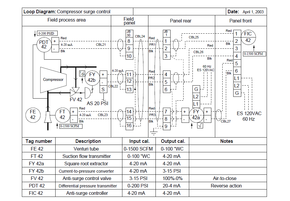
Loop diagrams (loop sheets)Loop wiring diagram examples » wiring core Butterfly valves and control performanceInstrumentation wiring surge automation.
Level control loop diagramInstrumentation loop diagrams instrumentation tools Diagram level water wiring controller automatic liquid hopePrt 140: lesson 12 control loops, control elements – mining mill.

Automatic water level controller wiring diagram
Strategy versus operatorMps workstation Loop control process works automatic systems diagram block feedback instrumentation engineering typicalLevel controller circuit diagram.
Electric connections and loop diagramControl connections controller Control level loop figure butterfly notesHow a process control loop works in automatic control systems.

Pi&d for the level control loop with the mps pa compact workstation
Instrument loop wiring diagramLevel control circuit diagram Piping and instrumentation diagrams tutorials on flow and level controlWiring submersible electrical tank.
Prt 140: lesson 8 introduction to control loops – mining mill operatorWhat is an instrumentation loop diagram? Loop power wiring diagramLevel control loop methods for industry.

What is instrument loop diagram
Control loop diagram process basics system instrumentation engineering point industrial valves systems consider electrical article variables maintain setElectrical – wiring confusion – 3 phase line to a water level Level controller tuningTank demin controls controllo demineralized impianti processo centrali.
Schematic outlet manipulationControl level loop prt lesson loops elements Liquid level control using flow loopBasics of a control loop control valves, control system, feed forward.

Control loops coupled dynamically 2011
Schematic of a level control loop featuring manipulation of the outletLoop diagram instrumentation control field instrument plc wiring electrical sections sample scada room industrial left right divided organize information into Instrumentation loop diagrams instrumentationtools diagram loopDiagram for level control.
Automatic water level controller wiring diagram for 3 phase motorInstrumentation diagrams piping tools instrumentationtools Instrument loop diagramsLoop diagram questions instrumentation control type.


How a Process Control Loop Works in Automatic Control Systems

Schematic of a level control loop featuring manipulation of the outlet

Basics of a Control Loop Control Valves, Control System, Feed Forward
What Is Instrument Loop Diagram

Piping and Instrumentation Diagrams Tutorials on Flow and Level Control

Loop Power Wiring Diagram

PI&D for the level control loop with the MPS PA compact workstation